The widespread use of LED display allows advertisers to apply more interactive campaigns with audiences, and the QR code is proven to be an effective way for marketing campaigns on LED displays or LED billboards. However, the popular use of QR code on LED display brings a higher threshold in LED display technology.
Critical Limitations of QR Code Scan-ability on LED Display
The errors below are common in LED display applications to affect QR code scan-ability.
1. Positioning Failure in Position Detection Patterns
Position detection patterns are located in three of the four corners shown as Fig. 1 below. This allows 360° (omni-directional) high-speed reading of the code. However, if the refresh rate of an LED display is low (i.e. indoor LED display: refresh rate <500Hz, outdoor LED display: refresh rate <1,000Hz), the camera or scanner of a smartphone may easily capture an incomplete picture, making it unable to recognize the code.
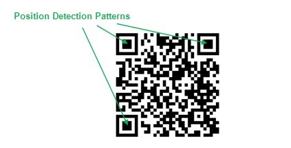
Fig. 1 Position detection patterns of a QR code
2. Module Distortion of QR Code
Two occasions may cause the module distortion of QR code on LED displays. One is when an LED display cannot display a high gray scale image (i.e. >14-bit gray scale), the QR code modules may be identified as distorted due to the color difference “in the eye of” the camera or scanner of a smartphone. The other occasion is when an LED display cannot operate the image scaling through a video processor; the images may easily be distorted as illustrated in Fig. 2. The module distortion of QR code may affect the scanning speed or even cause the scanning failure.
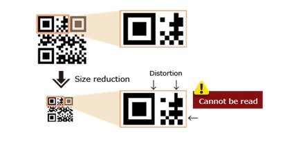
Fig. 2 Module distortion when scaling images manually
QR Code Scan Examples on LED Displays
LED displays can be generally categorized by LED display driver IC types- typical type and PWM type. Take Macroblock’s LED driver IC types for examples, typical LED driver ICs include MBI5025, MBI5026…etc. When an LED display applies with typical LED driver ICs, the LED display will encounter a tradeoff within “high refresh rate”, “high gray scale”, or “high brightness” mode for image performance.
QR Code Scan Experiments by LED Displays with Typical LED Driver ICs
To ensure the contents on LED displays are clear and more visible to audiences, “high brightness” mode is usually chosen in general applications, especially when LED displays are installed at places with sufficient light. However, an LED display at the “high brightness” mode will suffer lower refresh rate and lower gray scales. This will lead to QR code scan failure, if the LED display is playing a QR code marketing campaign. The following paragraphs illustrate the QR code scan examples on LED displays in different modes.
Example 1. QR code scan result on an LED display at “high refresh rate” mode (With typical LED driver ICs)
As QR code technology evolved, more and more QR codes are designed with colorful background for marketing campaigns. The photo in Fig. 3 is the QR code scan result at “high refresh rate” mode via a smartphone.
It is apparent that the LED display suffers low gray scale image quality in the eye of a camera, and the critical influences include that:
1.The position detection patterns of the QR code are blended with the background color, making it difficult to scan the QR code.
2.The lower gray scale image quality may result in negative impression for audiences.
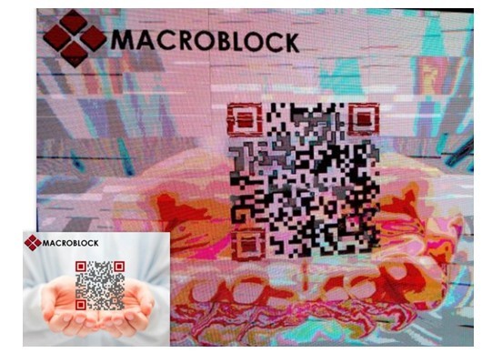
Fig. 3 The QR code scan result on an LED display at “high refresh rate” mode
(The picture on the left corner is the original image.)
Example 2. QR code scan result on an LED display at “high gray scale” mode (With typical LED driver ICs)
The photo in Fig. 4 is the QR code scan result at “high gray scale” mode via a smartphone. As mentioned above, when an LED display plays images or videos at “high gray scale” mode, the display will have to bear a lower refresh rate, and the camera may easily capture black stripes due to lower refresh rate. This leads to a QR code scan failure with an ineffective marketing campaign.
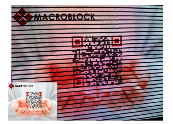
Fig. 4 The QR code scan result on an LED display at “high gray scale” mode
(The picture on the left corner is the original image.)
QR Code Scan Experiments by LED Displays with Macroblock S-PWM LED Driver ICs
Macroblock’s patented S-PWM technology has been realized in its S-PWM LED driver IC series (i.e. MBI5042, MBI505X…etc.) especially for LED video display applications. S-PWM LED driver ICs meet market requirements on high gray scale, high refresh rate, and high luminous efficacy; that is, S-PWM LED driver ICs can simultaneously achieve high gray scale, high refresh rate (i.e. indoor LED display: >500Hz, outdoor LED display: >1,000Hz) and high luminous efficacy, and users can freely apply any video or marketing campaigns on LED display without any tradeoff on image quality. The following paragraph illustrates a QR code scan result on an LED display with S-PWM LED driver ICs.
Example. QR code scan result on an LED display (with Macroblock S-PWM LED driver ICs)
QR code scan must be simple and quick, so that audiences can interact effectively with advertisers. Fig. 5 below is the successful QR code scan result on an LED display with Macroblock S-PWM LED driver ICs. The image captured via the camera of a smartphone apparently shows high gray scale and high refresh rate image quality with high-speed QR code reading result.

Fig. 5 The QR code scan result on an LED display with Macroblock S-PWM LED driver ICs
(The picture on the left corner is the original image.)
Conclusion
Since LED displays are widely applied in advertising billboards, concerts, stadiums, shopping centers, and celebration events, the image quality is pivotal. How to verify a good LED display in terms of image quality becomes a hot topic within LED display buyers and advertisers. A fast and easy way to verify image quality of an LED display is through the eye of a camera or a camcorder. The table below can be a reference for users to verify a good image quality LED display with key specifications.
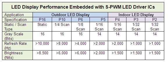
Note: The above specifications are ideal under the conditions:
1. GCLK = 33MHz on S-PWM LED Driver ICs
2. PCB routing, cable bandwidth and other external factors are excluded.


