A19, E14/17, E26/27 Bulb Lamp LED Driver Design
In Part III of Fairchild Semiconductors blog series on LED lighting trends we discussed MR11/16 Lamp LED Driver Design Challenges. Now we’ll look at A19, E14/17, E26/27 Bulb Lamp LED Driver Design.
Some bulb types are known as “Edison socket” and “candle lights.” The majority are incandescent light bulbs with CFL or LED replacements which gaining the majority of the application requirements.
A19, E14/17, E26/27 Socket Bulb Configuration
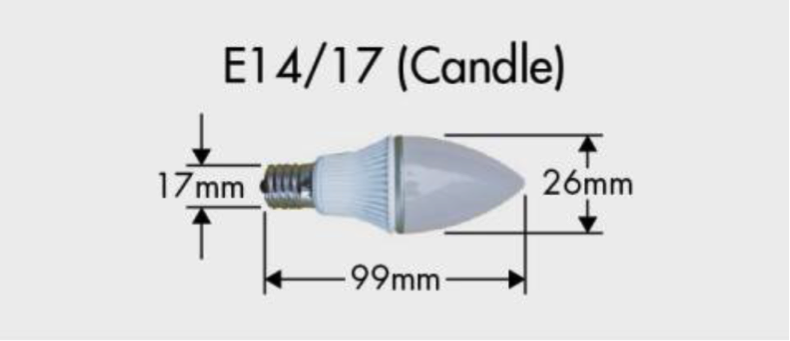
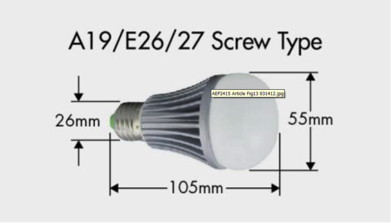
When input voltage is direct from the AC mains line, the socket types are: E14/17 (candle), A19/E26/27 (screw type) with the power rating of 1~5W for candle lights and 4~17W for the incandescent replacement. The form factor is shown in Fig. 1 and Fig. 2.
 |
|
Fig.-1.-Example-of-Candle-Type-L-99mm-D-26mm-E-17mm |
 |
|
Fig. 2. Example of Socket Bulb Type (L- 105mm, D55mm, B26mm) |
A19, E14/17, E26/27 Socket Bulb LED Driver Design Challenges
The LED driver design challenges for the candle light is the small PCB space. It is smaller than the MR lamp space and operates from AC input voltage lines. The incandescent lamp replacement targeted for a LED driver design has a larger PCB space than the candle lamp or MR type lamp, but the power rating is larger, so the LED driver is larger. The net effect is the PCB space is limited, similar to the candle lamp. PF and THD are almost mandatory for the socket bulb designs and there is the extra burden of dimmer operation.
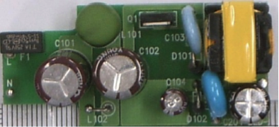
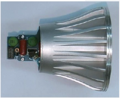
The PCB form factor for the E26/27 bulb with socket-side parabolic shape is socket side: 20 mm, LED module side: 35 mm, width: 70mm (see Fig. 3).
 |
 |
|
Fig. 3. Example E26-E27 PCB Form Factor |
Efficiency needs to be over 75%. Dimmer design requirements include being compatible with various holding currents, operating linearly over a wide range of light amplitude, and preventing flicker.
A19, E14/17, E26/27 Socket Bulb Fairchild Solutions
Isolation-type driver choices are preferred for safety. In this power range, the preferred LED driver solution is the flyback topology. With PF and THD becoming mandatory for candle lights, although it is a low-power application; many designers are using the single-stage flyback solution. The single-stage PFC flyback topology reduces PCB size because it can eliminate the input electrolytic bulk capacitor. A further reduction in component count is realized by using a single-stage Primary-Side Regulation (PSR) flyback solution. With its low BOM cost, isolated characteristic, PFC, and wide input voltage range; the PFC PSR flyback is poised to become the preferred LED driver topology.
 |
|
Table 1. Fairchild PSR Controllers |
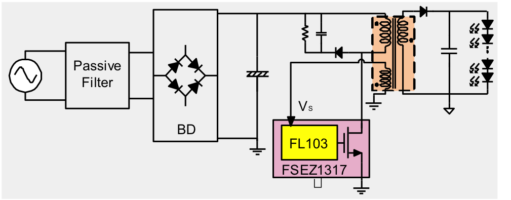
In the PSR topology, no secondary-side feedback is required; which eliminates the opto-isolator, the error amplifier (such as TL431), and the compensating and bias resistors and capacitors. Fig. 4 illustrate a simplified PSR schematic.
 |
|
Fig. 4. Primary Side Regulator Schematic |
The advantages of PSR flyback topology include:
§ The single-stage solution limits the number of components and ultimately fits into a smaller design space.
§ The FL103 50kHz operating switching frequency helps the flyback magnetic transformer fit within volume constraints.
§ The integrated MOSFET option with the FSEZ1317 reduces the component count, saving additional PCB space.
§ The reduction in components from a PSR topology helps meet cost reduction pressure.
§ No secondary-feedback circuits are needed, which creates an immediate reduction in components and an improvement in reliability (without counting the opto-isolator or TL431).
§ Fairchild’s PSR topology includes TRUECURRENT™ technology, the industry leading-edge constant-current performance of <±3 %, which provides consistent high-quality light radiation.
§ The solution is isolated.
§ The single-stage flyback topology can meet
PF and THD requirements.
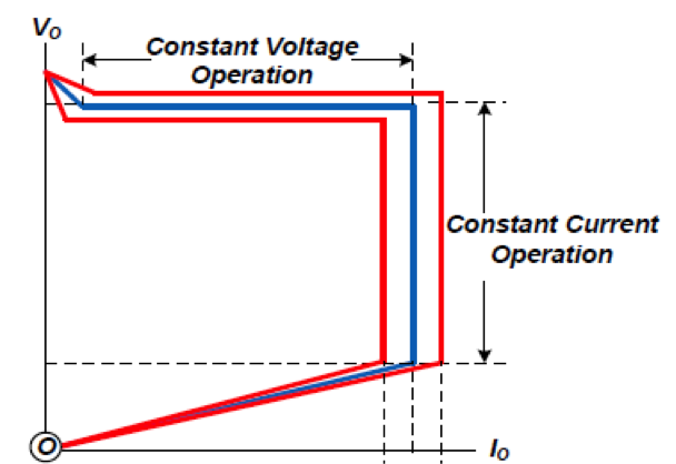
The PSR flyback operates in two modes, Constant Voltage (CV) and Constant Current (CC). LED drivers should operate in the CC Mode to better control the light output from the LED string. Fig. 5 shows the I-V characteristics of the PSR regulated flyback.
 |
|
Fig. 5. I-V Output Characteristics of a PSR Flyback LED Driver |
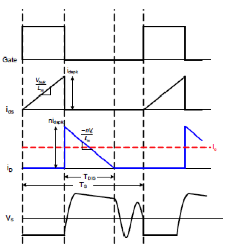
Discontinuous Conduction Mode (DCM) is preferred for PSR since it allows for better output refualtion. The typical waveforms are shown in Fig. 6.
 |
|
Fig. 6. Waveforms of DCM Flyback Converter |
When operating in Constant Voltage regulation mode, during the inductor current discharge time tDIS, the sum of the output voltage and diode forward-voltage drop is reflected to the auxiliary winding side. Since the diode forward-voltage drop decreases as current decreases, the auxiliary winding voltage reflects the output voltage at the end of diode conduction time tDIS. By sampling the auxiliary winding voltage at the end of the diode conduction time, the output voltage information is obtained.
When operating in Constant Current regulation mode, the output current can be estimated using the peak drain current IPEAK and the inductor current discharge time tDIS because the output current is the same as the average of the diode current in steady state. With Fairchild’s TRUECURRENT™ technology, constant current output can be precisely controlled.
In the next and last installment of this five part blog series we’ll PAR16, 20, 30, 38 Lamp LED Driver Design.
Please visit our LED resource page to learn about Fairchild’s LED lighting solutions. In Part IV we’ll blog about A19, E14/17, E26/27 Bulb Lamp LED Driver Design.
(Authors: James Lee, Brian Johnson and Richard Chung of Fairchild Semiconductor.)


