(Authors: Zhaojun Liu, Professor at School of Electronics and Information Technology, Sun Yat-sen University and Ke Zhang, Researcher, SYSU-CMU Shunde International Joint Research Institute)
Micro-LED a light emitting diode driven by electric currents, similar to traditional LEDs in display applications it can be driven using passive matrix or active matrix. A third current driving method is the new semi-active matrix driver, which uses a completely different method compared to existing models. Below we will introduce three different circuit designs and their basic theories.
What is passive matrix?
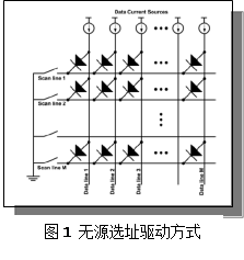
Passive matrix align LED pixels in an array where the P-electrode is connected to the Data Current Source, and the N-electrode in every LED pixel is connected to a scan line.
When the current passes through a selected points on the Y row scan line and X row scan line the intersecting point is labelled (X, Y), resulting in the immediate light up of the LED pixel. Pixels and points on the entire display are scanned at high speed to reveal the entire display image, such as those seen in image 1. As seen in image [1,2] this kind of scan structure is simple and easy to achieve.
 |
|
Image 1: Passive matrix circuit and driver layout. (All images courtesy of Zhaojun Liu and Ke Zhang) |
This is not the most complicated connection (only X+Y is connected lines), which causes large parasitic capacitance, greatly lowering the passive matrix efficiency, the short light emitting intervals on the XY which results in declined brightness. This also leads to crosstalk, where pixels interfere each other, and leads to higher frequency requirements in the scanning signal.
Another form of interference in passive matrix, is when an additional latch is added in the scanning process, where all the pixels in the X row is scanned into the signal (Y1, Y2…to Yn), and is saved in the latch.
When the X row is first selected, the above Y1-Yn signals are downloaded onto the pixel [3]. This type of driving method can lower the array driver’s signal frequency, increase the display’s brightness and illuminating qualities. One of its major flaws, though is its complicated connection method, crosstalk, and difficulty in saving pixel communication signals. Active matrix offer a good solution to the above issues.
What is active matrix?
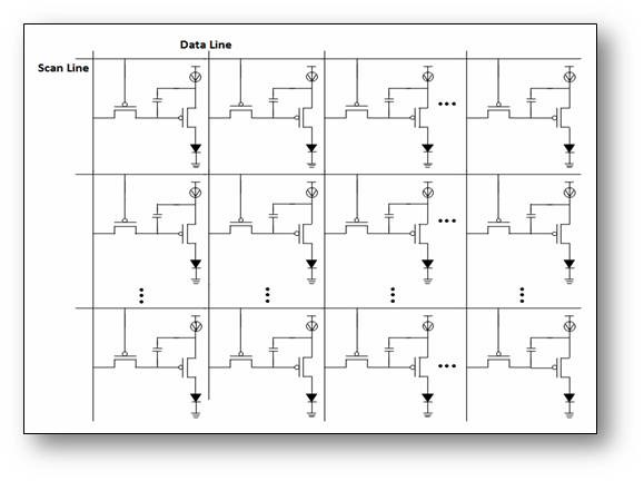
Every micro-LED pixel has an independent driver in an active matrix, and the electric current is supplied by the driving crystal diode. The basic active matrix current design comprises of two transistors and one capacitor (2T1C), as seen in the marked area [4] on graph 2.
 |
|
Image 2. Active matrix solution design and layout. |
Every pixel on the IC design will use two transistors to control the electric output, T1 is the where the current first travels through, and is used to turn on or turn off pixels. T2 is the second transistor, where it provides a stable current to micro-LEDs when the voltage source passes through the parallel connected conductors in the frame.
The circuit includes a capacitor to save the Vdata, and after the pixel component completes scanning the signal pulse, the saved capacitor can still maintain T2 gate and electric voltage. This supplies micro-LED pixels driving current until the frame ends.
Every pixel uses at least two transistors to control the electric output, including T1 which is chosen to control the pixels of the current to turn it on or off. The T2 is a driving transistor that when passing through the parallel connected power sources within the frame time period, can provide micro-LED a stable power supply.
2T1C driving current was originally used in active matrix micro-LEDs, and is a basic pixel current structure, but it is not easy to achieve. Basically this is a type of Voltage Current Controlled Current Source (VCCS), but the micro-LED pixel is a component that allows electric current to pass through, so it is more challenging for it to achieve grey control in displays. We will discuss about the issue of grey scale and full-color in micro-LEDs.
Zhaojun Liu, Professor at School of Electronics and Information Technology at Sun Yat-sen University previously had tested a type of 4T2C micro-LED pixel current, which uses Current-controlled Current Source (CCCS) to achieve advantages in gray scale control.
What is semi-active matrix method?
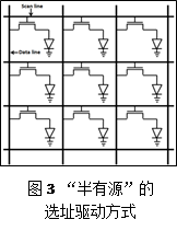
Another type of driving current method is semi-active matrix, which uses a single transistor to drive the micro-LED pixel and driver current for instance as seen in graph 3. This helps prevent crosstalking between pixels.
 |
|
Image 3. Semi-active matrix layout and design. |
Comparison between the three matrixes:
Compared to passive matrix, active matrix micro-LEDs have a distinctive advantage, where the active micro-LEDs led to the electric current and driver’s illumination. A breakdown can be seen below:
1. Active matrix have more powerful driving current capacities, and can drive currents to large areas, while passive matrix driver capacities are limited by external IC driver capacities, limiting the driven area’s image resolution.
2. Active matrix micro-LEDs are brighter have better uniformity and contrast performance, compared to passive matrix that has limited capacity due to its external IC driver design. Every pixel’s brightness is affected by alternating rows pixel brightness. In general, the same row of micro-LED pixels share the external driver IC or multiple driver currents.
Hence, when the number of pixels that light up and intensity of the brightness are different in each row, it is because of uneven flow of electric current into each LED pixel. This issue becomes aggravated in large display applications, for instance LED TV and large LED displays. The larger the screen the more challenging for each micro-LED to maintain uniform brightness.
3. Active matrixes are very efficient and can lower power consumption, large displays require higher pixel density, hence it will be important to reduce the LED size, and the display’s drivers required electric voltage increases significantly, the large power loss from scanning each array and row causes the droop in efficiency.
4. Highly independent control capacities: In passive matrix higher driving voltages and currents also will create issues known as crosstalk, in other words in a passive matrix LED arrangement the driving current in theory will only choose LED pixels for current to pass through. The surrounding pixels will be affected by electric pulses, which lead to declining display quality. Active matrix micro-LEDs on the other hand will allow the current to pass through the power transistor driver, and the pixels on the IC effectively prevents crosstalk.
5. Higher resolution. The active matrix is more suitable for high pixels per inch (PPI) micro LED displays.
The last semi-active driver can effectively avoid crosstalking, but similar to other IC currents without capacitors each driving current signal needs to be individually adjusted, and cannot achieve the same advantages as active matrixes.
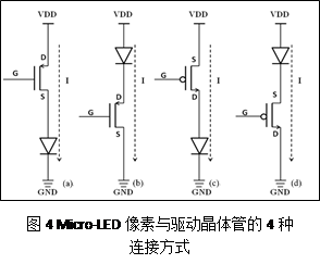
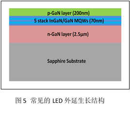
Micro-LEDs grown on sapphire substrate based epiwafers for instance can connect to transistor T2 using the fourth solution presented in image four, but LED epiwafers growth structure is a p-GaN layer while the surface is a n-GaN layer substrate, such as indicated in image 5.
 |
 |
|
Top: Image 4 shows four solutions for connecting the micro-LED to the transistor. Bottom: Image 5 indicates illustrates common LED epiwafer structures. |
From a technological angle, the driver transistor’s output connected to the micro-LED’s P-type is reasonable, as seen in (a) and (c) in image 4. In image 4(a) the micro-LED pixel is connected to the N-type transistor’s source, while the epitaxial growth and equipment technology and component depreciation will eventually cause uneven current distribution, which affects the micro-LED’s electrical properties, and uneven distribution that directly impacts the LED’s driving transistor’s threshold voltage (Vgs).
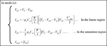
In image 4(c) the micro-LED pixel is connected to the P-type transistor’s drain to avoid the above effects, while the electric current and voltage relationship can be observed in image 6. Hence, micro-LEDs are more suitable for p-type pixel driving currents.
 |
|
Graph 6. Micro-LED transistors current and voltage relationship. |
Reference:
[1]. H. X. Jiang, et al., Applied Physics Letters, 78 (9), p. 1303-1305, 2001.
[2]. C. W. Keung and K. M. Lau, EMC 2006 (PA, USA).
[3]. D. Peng, et al, IEEE J. Display Technol., Vol. 12, Issue 7, pp. 742-746, 2016.
[4]. K. Zhang, et al, IEEE T. Electron. Dev., to appear.
[5]. Z. J. Liu, et al, IEEE Photon. Technol. Lett., Vol. 25, no. 23, 2013.
[6]. K. Chilukuri, et al, Semiconductor Science and Technology, 22 (2), p.29, 2007.
(Editor’s note: This is an authorized publication of the article, please contact the authors if you would like to directly repost content or use the article for publication purposes)


