Roy Mi, Senior AE & Technical Marketing Manager at Fairchild Semiconductor introduces the company's LED driver with power factor correction in this latest blog entry. Please see below for more details:
The consumer electronics market, and the LED driver market in particular, have been developing rapidly in recent years. These markets are demanding power supplies/drivers with lower power consumption in shrinking form factors, as well as ultra low cost. Furthermore, due to the ever-increasing requirement for improved power quality, the use of power factor correction (PFC) circuitry for these devices is almost mandatory. Today, among various circuits, Flyback is the most attractive topology for these applications because of its simplicity. It provides the isolation, start-up, and the various other protections with one single switch. When it operates in discontinuous-conduction mode, a unity power factor can be achieved as well by using a simple constant on-time control.
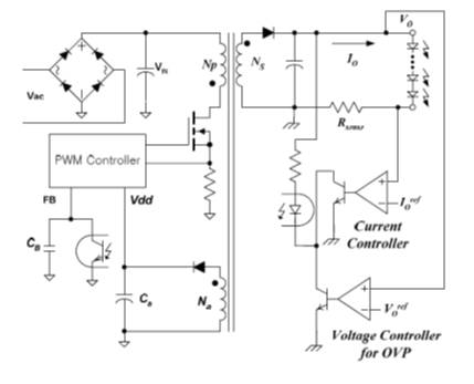
Traditionally, a constant current LED driver for LEDs is implemented using an isolated Flyback converter with an output current regulation circuit as shown in Figure 1. The actual LED current is measured using a sense resistor and then compared with a reference to generate error voltage. The error voltage is transferred to the primary side through an opto-coupler and used to control the duty cycle of the primary side switching device. Although this allows excellent LED current regulation, the output regulation circuitry requires an optocoupler, reference voltage, and sense resistor, which increases system cost and deteriorates overall efficiency.
 |
|
Figure 1: Conventional Secondary Side Regulated LED Driver. (All image courtesy belong to Fairchild Semiconductors) |
Primary-side regulation (PSR) can be an optimal solution to minimize the cost for LED drivers. This technique precisely controls LED current in the secondary side with the information in the primary side of the driver only. This not only removes the output current sensing loss but also eliminates all secondary feedback circuitry. This facilitates a higher efficiency offline LED driver design without incurring tremendous costs. This technique also regulates the LED driver output voltage without secondary feedback circuitry, which acts as an open lamp over-voltage protection guaranteeing better reliability of the driver.
 |
|
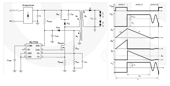
Figure 2: Primary Side Regulated LED Driver and its Typical Waveform. |
Figure 2 shows the simplified circuit diagram of a primary-side regulated Flyback converter as well as its typical operation waveform. The key of primary-side regulation is how to obtain output voltage and current information without directly sensing.
During the diode conduction time, the sum of the output voltage and the diode forward-voltage drop is reflected to the auxiliary winding side as (VO+VF)*Na/Ns. By sampling the winding voltage at the end of the diode conduction time, the output voltage information can be obtained. The output current (Io) can be estimated by using the peak drain current (Ipk) of the MOSFET and the discharging time (tDIS) of the inductor current because output current (Io) is same as the average of the diode current (ID) in steady state. The output current estimation identifies the peak value of the drain current with a peak-detection circuit and calculates the output current using the inductor discharging time and switching period (ts). This output information is compared with an internal precise reference to generate error voltage (VCOMI), which determines the duty cycle of the MOSFET. With Fairchild’s innovative TRUECURRENT® technique, the constant output current can be precisely controlled.
 |
With detected output voltage and current information, the control can be accomplished by the conventional feedback compensation method. Generally, Discontinuous Conduction Mode (DCM) operation is preferred for primary-side regulation. It features with better output regulation as well as unity input Power Factor (PF).
Related Links:
Want to learn more about primary-side regulated Flyback with PFC? Download our app note: High-Power Factor Flyback Converter for LED Driver with FL7732 PSR Controller, AN-9750.pdf


