Introduction
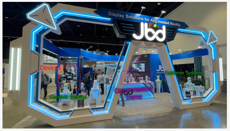
At SID Display Week in May 2024, MicroLED maker Jade Bird Display (JBD) had a large booth that showed their devices, a number of customer systems, and a “compensation demo.” JBD offered to loan me their compensation demo. After sending me one of the demos from SID and my taking many pictures to evaluate it, JBD informed me that they would be able to send me a newer demo in a couple of months, so I decided to wait for the newer system before reporting my results. Between the availability of the systems and my travel, many months have passed.
This article starts with quite a bit of “background information,” which I think is helpful in understanding the results. Perhaps the most controversial issue is that JBD says their compensation is based on both eyes. I felt the need to add some information on “Binocular Rivalry,” which discusses how human vision responds to seeing different content in each eye. Human vision is complex, to say the least, and while I think what JBD claims is mostly true, it oversimplifies what people see.
All images in JBD’s demo were pre-loaded into the demo system. JBD’s current devices have a more limited real-time correction built into the display and controller. The stills in the demo were pre-processed to demonstrate what will be possible in real-time with their new chipset. JBD allowed me to submit a series of test patterns that they added to their set of demo images, which I appreciate. Still, I couldn’t try any new test patterns based on my findings (which I often do with other headsets when I see an effect that I want to investigate further).
I should also note that the demo systems did not have the full heat-sinking capability that would be incorporated into a product. This limited the number of bright pixels, particularly red ones, that could be shown in a single image.
I also just realized that in all the back-and-forth with JBD on getting their demo system, which I thought would happen soon after Display Week, I missed reporting on MicroLED and other display technology at Display Week. I plan to make up for that soon. I also need to finish reporting on DLP’s use of “pixel shifting” for AR headsets using PoLight’s Twedge Concept. I want to get my backlog of information cleaned up before CES in January 2025.
Meeting at CES 2025
Speaking of CES 2025. If you or your company schedule a meeting with me at CES 2025, I can be reached at meet@kgontech.com).
JBD Dominates in MicroLED-Based AR Glasses
JBD is the only company I know of that is shipping MicroLEDs, and the only ones I have seen in any headset product or even prototype. At the same time, Meta CTO Andrew Bosworth stated in videos that Meta “designed” Orion’s MicroLEDs, and it is most likely that Jade Bird Display is making Orion’s MicroLEDs. It has been widely rumored that Meta’s 2020 MicroLED deal with Plessey fell apart (example: https://www.microled-info.com/meta-announces-10000-ar-glasses-powered-microled-microdisplays), and there are no other likely suspects. Perhaps Meta got a change in resolution to make it a custom part. It appears Meta “designed” the MicroLEDs in a similar way that Apple “designed” the Micro-OLEDs used in the Apple Vision Pro when it is known that Sony manufactured the Micro-OLEDs for Apple.
PlayNitride has demonstrated a full-color MicroLED display using blue MicroLEDs with Quantum dot red and green color conversion with a Lumus Waveguide (but not in a headset) at AR/VR/MR 2023 (see MicroLEDs with Waveguides (CES & AR/VR/MR 2023 Pt. 7)). PlayNitride has continued advancing its efforts with quantum dot color conversion MicroLEDs. Still, I have yet to see a headset.
JBD’s booth featured AR glasses from multiple companies, including TCL’s Ray New X2 (full-color 3-chip X-cube) Ray Neo X2 and several monochrome (green) AR glasses, including Vuzix Z100, LAWK’s Meta Lens, MyVu AR, and INMO’s Go. I have also seen JBD MicroLED-based monochrome AR glasses from Oppo and, more recently, Even Realities announced their small form factor AR glasses Even Realities G1: Minimalist AR Glasses with Integrated Prescription Lenses.

JBD’s Current and Future Lineup
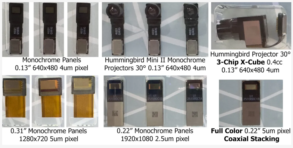
All the JBD MicroLED-based AR glasses to date use its monochrome 640×480 MicroLEDs with a 4-micron pixel. JBD offers projector optics for both single devices and has gone through a few generations of 3-Chip with X-Cube color combiners. JBD has been talking about 1280×720 monochrome devices with 5-micron pixels and monochrome 1920×1080 devices with 2.5-micron pixels for a few years, and JBD states that they plan on shipping devices to headset companies with 2.5-micron pixels for use in prototypes in 2025. JBD JBD sells MicroLED panels, both with and without the optics, as shown below.
As I have discussed before, including in TCL and JBD X-Cube Color and our recent AR Roundtable Video Part 2: Meta Orion Technology and Application Issues, combining three monochrome panels to form a full-color image is a challenging alignment problem that is costly to manufacture. Most laymen will think about the horizontal and vertical alignment. Still, the more complex problem is aligning the panels in all dimensions, or the individual colors will not be in focus across the image. I think everyone in the industry believes that some form of “monolithic” approach will be required in the long run for MicroLEDs to be used in high volumes. I discussed the most well-known approaches to single-chip-full-color MicroLEDs in MicroLEDs with Waveguides (CES & AR/VR/MR 2023 Pt. 7). Among those approaches is the “stacked LED” method, which grows the various Red, Green, and Blue LED crystal layers on top of each other.
JBD Single Chip
JBD has developed and is sampling a stacked pixel device, but I have not personally seen it running. Unlike others that make the red, green, and blue LEDs all in variously doped Indium gallium nitride, JBD uses AlInGaN for the blue and green LEDs and AlInGaP for red. While red can be made in InGaN, it is generally not very efficient and high-yielding, whereas AlInGaP is more “natural” when making red. JBD is demonstrating that they have the process capability to mix the two types of LED crystal layers.

It’s not clear when the stack LED approach will be better than the 3-chip method, at least for the immediate future. Perfecting the manufacturing of the complex process will likely take some time. The stacked approach limits the emission area of all three LEDs, and light from the lower layers will be blocked/lost by the upper layers. Then, there is the major issue of heat being trapped by the middle layers and LEDs heating each other. I discussed the various approaches to making full color with MicroLEDs in MicroLEDs with Waveguides (CES & AR/VR/MR 2023 Pt. 7), and each approach has its advantages and issues.
Display Resolution and Utility
The waveguide (from an unspecified manufacturer) supports an approximately ~30-degree (diagonal) FOV. The JBD 640×480 3-Chip X-Cube projector has about 26.6 pixels per degree of angular resolution. This resolution is the same as a 1987 IBM PC VGA display. It is 1.5x more total pixels than a 44mm Apple Watch 10 (416 by 496 pixels), with that watch having about 10 degrees FOV and ~65 pixels/degree when held about 300mm (~12 inches) away from the eye.
With more and larger pixels, the display is arguably capable of displaying about twice the usable information as the 44mm Apple Watch. This may be mitigated due to the watch having a black background while the glasses are seen against whatever the user is looking it. Still, the contrast and overall image quality will be limited due to the fact that it will be a see-through display and due to color variation with the waveguide. The image quality is more than good enough for looking at messages, thumbnail photos, short videos, and limited web browsing. Still, it is no replacement for a smartphone’s much better display.
Demo Systems, Caveats, and Overall Impression
First, I want to give the usual warnings about this being a demo system. I was loaned one of a few demo systems, not a product bought at random. I have no idea whether the display projector and its displays were cherry-picked, what effort or degree of automation was applied to compensate, or whether it could be replicated in production.
It is important to understand that the displays and optics are going into optical see-through AR glasses. As such, the absolute image quality does not need to be perfect, as it will be seen using whatever is seen in the real world as the background/black.
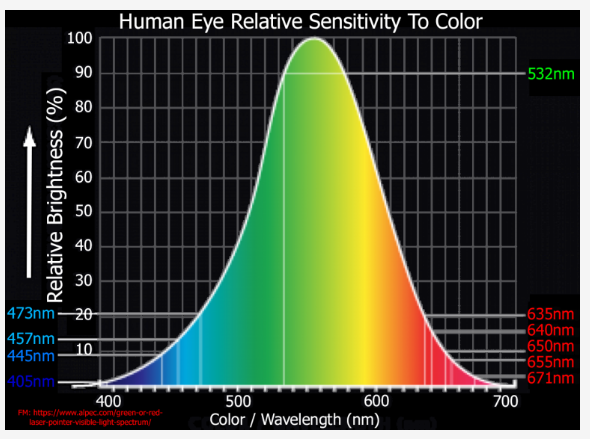
For informational-type AR information, while perfect color is not essential, it is often important that colors don’t vary so dramatically that saturated colors cannot be recognized. With see-through displays, when colors are used to add meaning, they need to be saturated and bright to stand out reliably; subtle color variations are pointless against a real-world background. Commonly green=good, red=bad, and yellow=caution. It turns out that blue (~450-470nm) is almost invisible against anything in the real world as blue is low in “nits” (human perception of brightness) and is also low in human resolving power (there are relatively few blue cones in the eye). So, often, see-through displays use cyan (blue+green) instead of blue. Also, humans often have a hard time telling Magenta (blue+red) from red. If, as is common with many diffractive waveguides, the color transmission varies dramatically across the display, then if colors made up of multiple primaries (ex., yellow) are used to indicate something, they lose their meaning. In some areas of the FOV, some colors might not be reliably visible as they become dim.
Demura (display pixel correction) and Waveguide correction
Both OLED and LED display technologies have issues with each emitting element varying in brightness and color. The variations occur from pixel to pixel and across large regions of the display. Due to the way MicroLEDs are made, they are more susceptible to variation than OLEDs. A process called demura is used to correct for these inherent display variations (see, for example, OLED-Info’s Correcting OLED and MicroLED Display Quality to Improve Production Efficiency and Yields). Simply put, the methods typically use a camera to look at the display at various intensities and develop a table of corrections for each pixel. Things can get complicated with emissive displays where current and or heat (induced by current) across the display can also cause variations, which, in turn, are a function of content (a bright image generates more heat).
JBD’s compensation method tries to correct for the variation in MicroLEDs and color variation across the waveguides.
The diffractive waveguides have significant brightness and color variations
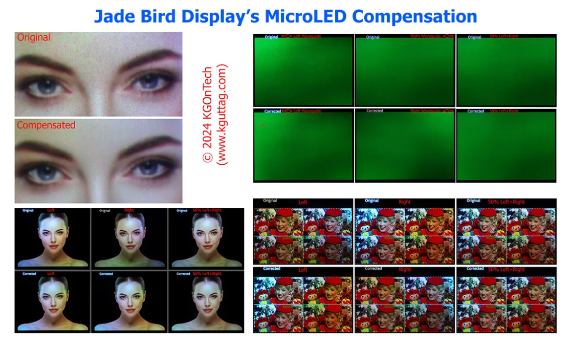
The waveguides inject light from temples or the upper left side of the left eye’s waveguide and the upper right side of the right eye, which results in a fall in brightness the farther the light travels from the injection corner. Complicating things further is that the light falloff varies by wavelength and is not completely symmetrical between the left and right. In particular, blue, while strong in the upper left corner of the left waveguide, becomes very dim in the lower right corner of the left waveguide. Below are pictures taken through the left and right waveguides for both the “original” and the compensated image, with the right-hand column showing the 50/50 combination of the left and right image simulating simple binocular fusion (averaging of the left and right view).
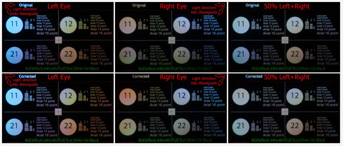
Generally, with these waveguides, the light falls off as it goes from top to bottom to the farthest corner of the waveguide. Blue and green are much brighter near the entrance and fall off significantly in the bottom corner opposite the waveguide. Blue and Green appear to fall off more than red (particularly on the Left waveguide).
Looking at the circle with the “11” in it, the left eye’s image is too cyan, and the right eye’s image is too red. Interestingly, in the corrected image, the left eye’s image has slightly less of a cyan tint, and the right eye’s image is redder than before the correction, as JBD’s algorithm is aimed at the fused/averaged image. Looking at the circle with “22,” which is in the darkest corner of the right eye (and farthest from the entrance grating), it is still a little reddish, even in the combined image. Loosely speaking, they can’t get enough light into that corner to compensate between both eyes.
Binocular Fusion and Rivalry
JBD said that their correction was based on binocular fusion. By this, they mean the simple average of the views of the left and right eye. Because the waveguides have somewhat left-to-right mirror symmetry, as shown in the previous set of images, it thus requires less correction to treat them as pairs. There is also so little light of various colors in the far corner from where the light enters the waveguides that it would mean driving the LEDs too hard in the corners or making the whole rest of the display much dimmer to try and balance the colors in a single waveguide. The somewhat mirror symmetry also allows them to add light to the areas of the left or right waveguide where it will be better transmitted.
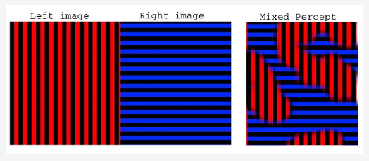
From FIGHT! Virtual Reality Binocular Rivalry
Binocular Rivalry, where each eye is presented with a significantly different image, color, or brightness between the two eyes. For a short article on the subject of human Biocular Rivalry, see FIGHT! Virtual Reality Binocular Rivalry, scroll down to part iv, and for more info, follow the links and their references.
Quoting from the study Humans Perceive Binocular Rivalry and Fusion in a Tristable Dynamic State:
The human visual system creates singular percepts from two monocular inputs. Small differences are “fused” into intermediate percepts, whereas larger differences are perceived from one eye at a time in a stochastic process called binocular rivalry (Wheatstone, 1838). These phenomena have provided insight to binocular combination effects (Blake and Fox, 1973; Blake et al., 1981) and perceptual suppression (Blake and Logothetis, 2002; Blake and Wilson, 2011) respectively.
This study concludes that “rivalry and fusion are multistable substates capable of direct competition rather than separate bistable processes.” In other words, the human vision system can switch between “fusion” and “rivalry.” The human vision system produces what people perceive as a single image based on a complex mixing of the left and right eye views where their views overlap.
From my study and personal experience, what is “seen” will vary with different people and factors, such as which eye is dominant, the luminosity (the vision will tend to see the brighter image), and what the person concentrates on in the image. When simply looking at the images in the demo with my own eyes, the color uniformity looked significantly better with both eyes than with just one eye or the other. Still, if I concentrated, I could see unique differences between the left and right eyes.
The blended average, while simplistic compared to the human vision system, is a reasonable approximation of what most people will see in terms of color variation when typically viewing images with modest color variation, which is what I will be using in this article.
JBD Appears To Do A Good Job of Correcting the MicroLEDs
From what I am seeing, JBD is doing a good job of correcting the MicroLEDs themselves. Below is a picture of a mostly white flower from the right (only) waveguide with both the original (uncompensated) and JBD’s compensation.
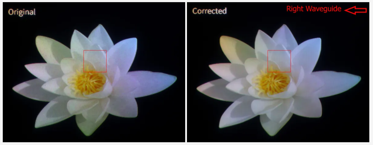
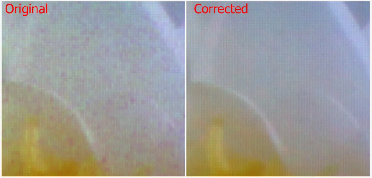
The next two images zoom in on the areas of the red squares above to show pixel-level detail with and without correction. Notice how all the pixel-level random “noise” is largely corrected.
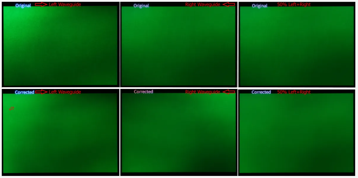
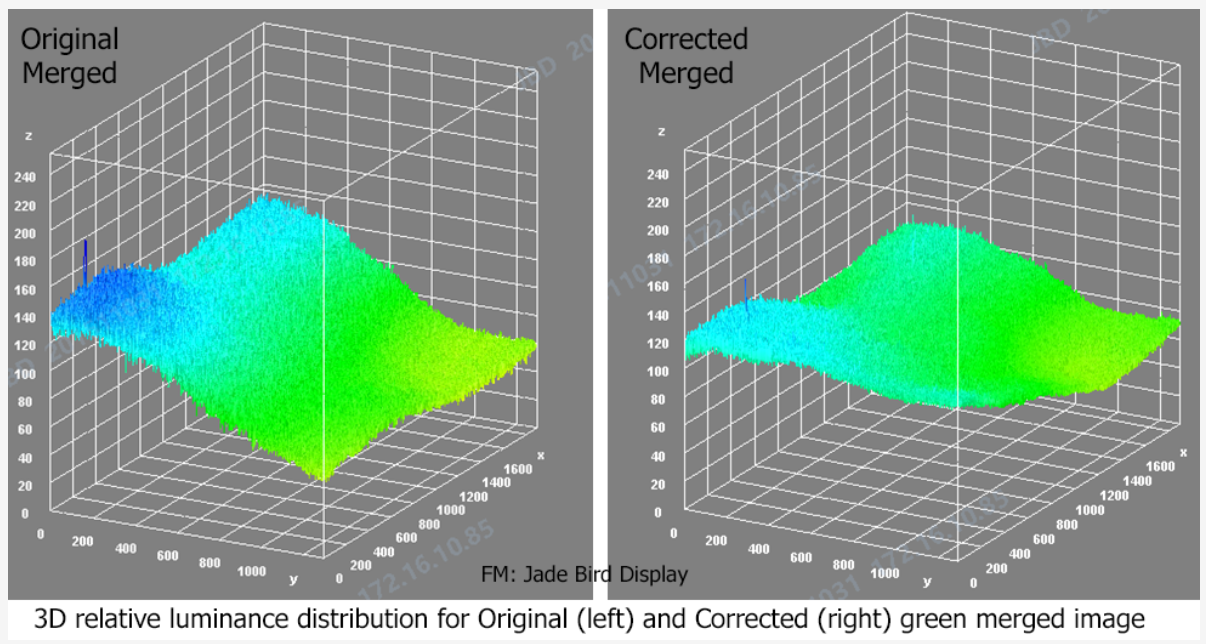
Next, we have a pure green image, once again with the left and right, and a combined image with both the origin (top row) and compensated (bottom row). In this image, we can better see both the pixel-to-pixel corrections and how the compensation is trying (but partially failing) to correct the waveguide over the whole FOV. This shows how the green light is falling off in the corner diagonally across from the entrance grating.
JBD provided me with a 3-D visualization of the Merge Original and Corrected image (below). These seem to agree with my camera results (right hand column above).
If you click on the image above, you will see a bright dot in the corrected left waveguide image (lower left image). The image below zooms into the upper left corner of the left eye’s waveguide for both the original and corrected image. While not perfect, it does a very good job of removing the major pixel-to-pixel differences. There was one “bug” in their correction where they overcompensated for a dark pixel, pointed to by the red arrow below in the medium (below left) and very high (below right) zoomed-in image images. It is not a big deal as this is a prototype.
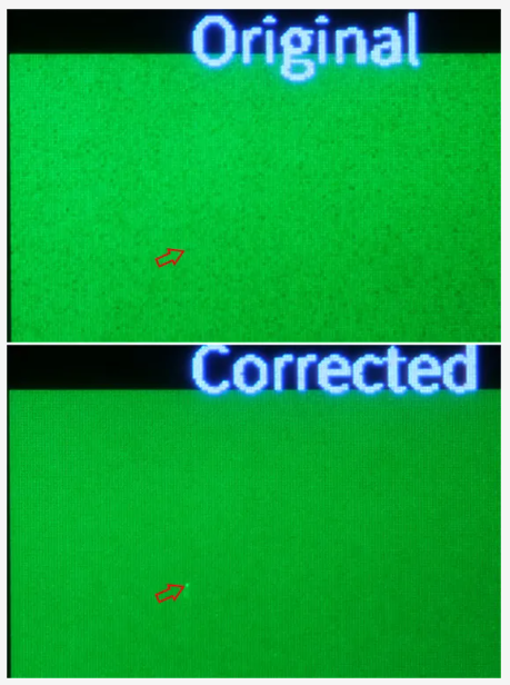
As discussed in the Binocular Rivalry section above, I could see the bright dot with my own eyes where it might not be visible in the Left+Right “averaged” image.
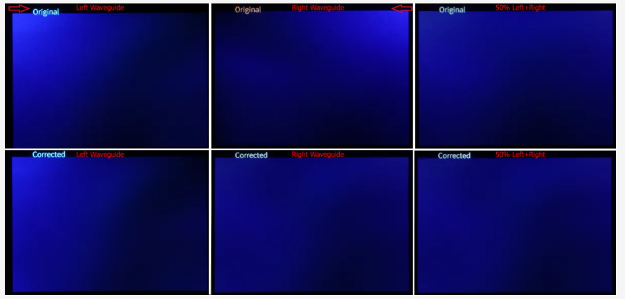
Below are the left and right waveguide images with and without correction for a flat blue image. This demonstrates how the blue light transmission varies through the waveguide. Compared to the flat green results above, the blue light seems to progress slightly worse from the input grating corner than the green.
Distinguishing Colors
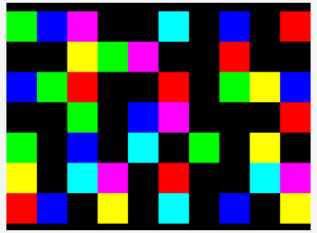
As discussed earlier, it is common to assign meaning to certain colors, such as Green = Good, Red = Bad, and Yellow = Caution. On the right is a test pattern that puts primary colors and those with two primary colors (e.g., Yellow = Red + Green).
I submitted a flat red image to JBD, but for some reason, it was not loaded into the demo system. As is evident from the earlier test patterns with white circles, the pattern of the red light is somewhat different from that of the blue and green.
Below are the various combinations of left, right, original, corrected, and (Photoshop) averaged images for the color squares. Because of the differences in the waveguide’s response to red and green, yellow becomes problematical to disguise from green (see, for example, the squares with the red rectangle). Magenta (red+blue) is problematical to distinguish from red. Even though the dimming of blue and green is similar, as can seen with the Green and Cyan squares in the white squares, distinguishing green from cyan can be problematic.
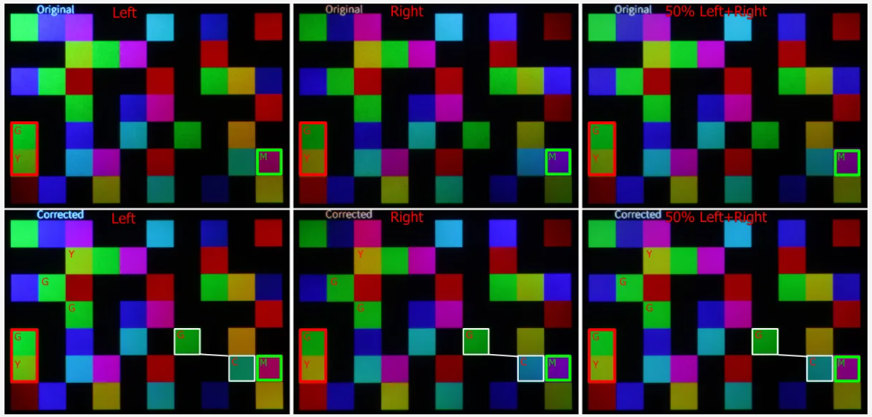
While the ability to distinguish colors is better in the corrected average of the left and right images (lower right image), as discussed in the Binocular Rivalry section earlier, the average is not what the human visual system will “see,” at least dependably.
Human Facial Tones

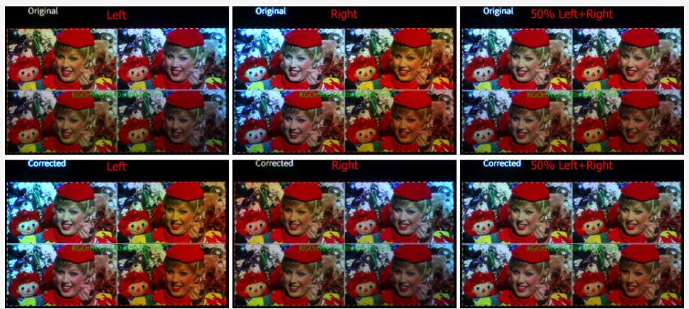
Humans are very sensitive to facial tones. It is thought that it is primordial sense to tell if someone is sick. Humans are not generally good at any other colors. As I have said for years, if I only see cartoon images and no human faces in a display demo, then likely as not, they can’t control the colors well. I have used the test image (right) for years, as it combines facial tones with some near-primary RGB colors and some dull white.
Below are the left, right, original, corrected, and averaged images. As with the color squares, the way the various primary progress in X and Y through the waveguide causes color shifts across the images. JBD’s compensation for the MicroLEDs plus the Waveguide does a reasonably good job when the left and right are averaged (bottom right). Still, as discussed in the Binocular Rivalry section, this is not exactly what the human will see.
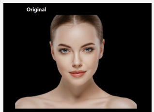
JBD had a larger image of a woman (right) that filled much of the screen. The images below show how the facial tones varied in a single picture.
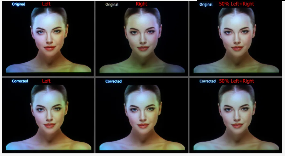
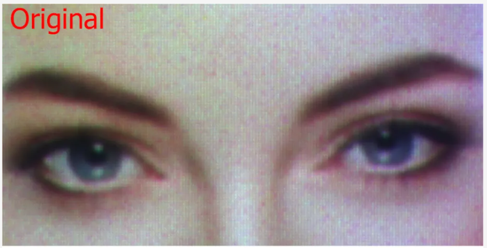
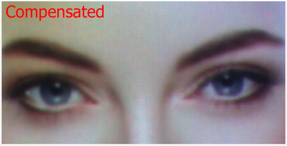
Below is a close-up of the right waveguide’s image for both the original and corrected/compensated image.
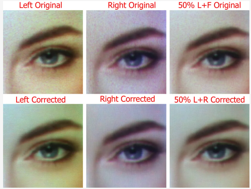
Below is a close-in crop of one eye with the common six-way comparison.
The Demos System’s Waveguides and Camera Alignment
JBD informs me that the waveguide’s eyebox is 10mm by 12mm, which is reasonably good (I don’t have the optical measurement equipment to test this spec. Compared to other waveguide optical systems I have photographed, the demo system waveguides seem to have a small sweet spot, at least in terms of color, with my camera equipment. The colors will shift, and my camera moves a few millimeters up or down or a slight change in angle. For all the pictures taken in this article, I adjusted the camera position for what I judged to be the best overall image as viewed through the camera. Below is a series of four pictures where I slightly moved the camera up or down from what I judged to be the best location.
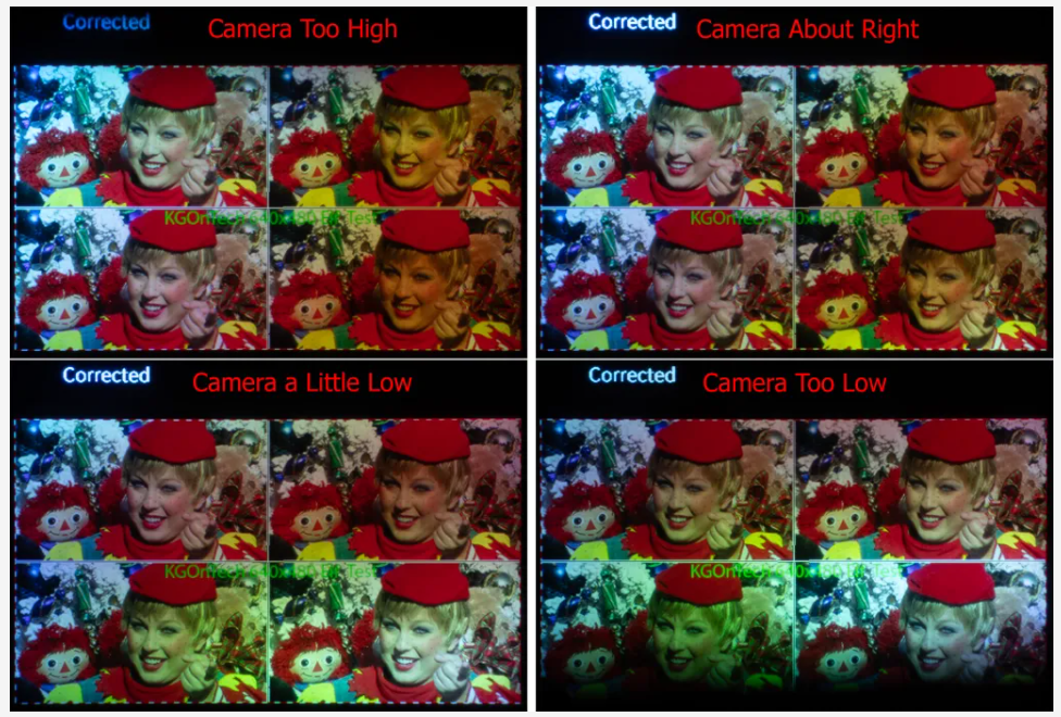
I checked that similar color changes occurred with my own eyes as I shifted my view slightly. I used a six-axis camera rig to try and align the camera in the sweet spots of the left and right waveguides.
Conclusions
Overall, I thought that JBD successfully demonstrated that they can correct the variations in their MicroLEDs. There didn’t seem to be any dead pixels or pixels that were so dim they could not be corrected. They also did a reasonably good job of aligning the color panels on the X-Cube (I plan to go into this more in the next article). The alignment and overall image quality were also good with TCL’s glasses using JBD’s MicroLEDs with an X-Cube (see TCL RayNeo X2 and Ray Neo X2 Lite). I want to repeat a caveat: my experiences are with one-off demo systems, and I have no idea whether they were cherry-picked.
The demo was not able to fully correct for waveguide variation due to the waveguide’s color non-uniformity (I don’t know whose waveguide was used). Additionally, the color shifts with the eye’s location relative to the waveguide. When you look at a photo of a person, you can tell who it is, but the person’s facial tones vary across the waveguide. For some applications where color is used to indicate warnings or other information, the non-primary color shift and dimming of primary colors across the waveguide could be an issue.
I would like to see JBD’s MicroLEDs coupled with different diffractive waveguides. As I noted in TCL RayNeo X2 and Ray Neo X2 Lite, I saw major differences between the RayNeo X2 and X2 Lite, which used waveguides from different companies. I would also like to see it with Lumus’s reflective waveguides, which are typically much more uniform in terms of color and brightness uniformity than the diffractive waveguides. Lumus also believes that they would be more than 5 to 7 times more efficient/brighter than a diffractive waveguide with MicroLEDs (I would like to see if this can be proven).
I have been following JBD’s developments since 2019, and they have made major progress in the manufacturing of MicroLEDs and the quality of the demo systems I have seen. Not to mention that they are the only company with customers shipping MicroLED-based AR glasses products. Below are macro photographs directly (no optics other than the camera’s macro lens) of a JBD green and blue display I took at CES 2020, where there were many dead/nearly dead pixels (click on the images to see the details).

TrendForce 2024 Micro LED Market Trend and Technology Cost Analysis
Release: 31 May / 30 November 2024
Language: Traditional Chinese / English
Format: PDF
Page: 160-180
TrendForce 2024 Near-Eye Display Market Trend and Technology Analysis
Release Date:2024 / 07 / 31
Languages:Traditional Chinese / English
Format:PDF
Page:164
|
If you would like to know more details , please contact:
|


 CN
TW
EN


